1
2
3
4
5
6
7
8
9
10
11
12
13
14
15
16
17
18
19
20
21
22
23
24
25
26
27
28
29
30
31
32
33
34
35
36
37
38
39
40
41
42
43
44
45
46
47
48
49
50
51
52
53
54
55
56
57
58
59
60
61
62
63
64
65
66
67
68
69
70
71
72
73
74
75
76
77
78
79
80
81
|
tags:: DXF-Internals
- [DXF Reference](https://help.autodesk.com/view/OARX/2018/ENU/?guid=GUID-34F179D8-2030-47E4-8D49-F87B6538A05A)
- This object is used to describe the clipping path for [[XREF]] and [[BLOCKS]] create by the [[XCLIP]] command
- The SPATIAL_FILTER object is attached to the [[INSERT]] entity via the [[Extension Dictionary]]
- The entity is supported from [[DXF R2000]] onwards
-
- ## Clip Boundary Geometry
- The group code 10 tags define the clipping boundary in [[OCS]] coordinates based on an xref scale of 1
- The [[OCS]] of the boundary path is defined by group code 210, the `extrusion vector`
- All examined samples have an `extrusion` vector of (0, 0, 1)
- The group code 11 is used to define the `origin` of the local coordinate system of the clip boundary
- All examined samples have an `origin` of (0, 0, 0)
- This is maybe just the elevation value stored in the z-axis like in the [[POLYLINE]] entity
- As the name implies - this is a 3D object. The spatial boundaries are defined by the front- and back clipping planes.
- Group code 40 defines the `front_clipping_plane_distance` (from the `origin` in direction of the `extrusion vector`)
- Group code 41 defines the `back_clipping_plane_distance` (from the `origin` in direction of the `extrusion vector`)
- **Important:**
- The group codes 40 and 41 should not be written if front- or back clipping is disabled
- [[AutoCAD]] doesn't like that
- In all examined samples created by [[BricsCAD]] was the OCS of boundary path aligned with the coordinate system of the block definition.
- The clipping path doen't have to be closes (first vertex != last vertex).
- Two vertices define a rectangle/cuboid where the sides are parallel to the x-, y- an z-axis.
- The clipping path is the geometry entered via the [[XCLIP]] command in OCS coordinates (=WCS in most cases).
- The boundary vertices are transformed into block coordinates by applying the `inverse_insert_matrix`.
-
- ## Visibility of the Clipping Path
- The [[HEADER]] variable [[$XCLIPFRAME]] defines if the clippining polygon is visible
- 0 = not displayed, not plotted
- 1 = displayed, not plotted
- 2 = displayed and plotted
-
- ## Clipping Status
- The group code 71 defines if the state of the block reference clipping
- 0 = off
- 1 = on
-
- ## Inverted Clip Boundary
- There is no flag to indicate an `inverted` clipping boundary
- The regular clipping clipping path, the outer triangle
- 
- The inverted clipping path, the inverted clipping path in red
- 
- The triangle itself is not included in the SPATIAL_FILTER entity anymore, instead the SPATIAL_FILTER entity got an extension dictionary:
- 
- 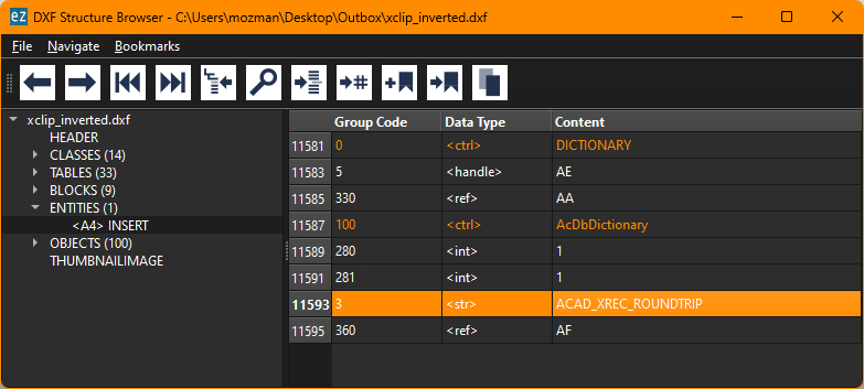
- This extension dictionary has an entry `ACAD_XREC_ROUNDTRIP` that references a [[XRECORD]] which has all the required information:
- 
-
- ## Stored Transformation Matrices
- The [[SPATIAL_FILTER]] entity includes two transformation matrices
- `inverse_insert_matrix`
- This is the inverse of the original block reference transformation.
- The original block reference transformation is the one that is applied to all entities in the block when the block reference is regenerated.
- `transform_matrix`
- This matrix transforms points into the coordinate system of the clip boundary
-
- ## Transformation
- [[Exploring the transformation behavior of SPATIAL_FILTER]]
- The [[SPATIAL_FILTER]] object has to be transformed along with the [[INSERT]] entity
- What attributes have to be transformed?
- None so far!
- `origin` is always (0, 0, 0) and remains always (0, 0, 0) in the cases I investigated
- The boundary vertices remain at the original location as the boundary path was entered via the [[XCLIP]] command.
- `ACAD_XREC_ROUNDTRIP` - not tested but I am sure they behave like the boundary path vertices - so nothing to do
- `inverse_insert_matrix` is not changed
- `transformation_martix` is not changed
- A test of copying clipped block references by `ezdxf` (created by BricsCAD) already works after implementing the SPATIAL_FILTER entity and without applying any additional transformations in the [[INSERT]].
-
- ## Creating the boundary path in BLOCK coordinates
- the `inverse_insert_matrix` is the identity matrix
- `transformation_matrix` is the identity matrix
- `origin` is (0, 0, 0)
- `extrusion` is (0, 0, 1)
-
- ## Creating the boundary path in WCS coordinates
- Transform boundary vertices into [[OCS]] coordinates
- the `inverse_insert_matrix` is the inverse of the [[INSERT]] matrix
- `transformation_matrix` is the identity matrix
- `origin` is (0, 0, 0)
- `extrusion` is the `extrusion` vector of the [[INSERT]] entity
|
