1
2
3
4
5
6
7
8
9
10
11
12
13
14
15
16
17
18
19
20
21
22
23
24
25
26
27
28
29
30
31
32
33
34
35
36
37
38
39
40
41
42
43
44
45
46
47
48
49
50
51
52
53
54
55
56
57
58
59
60
61
62
63
64
65
66
67
68
69
70
71
72
73
74
75
76
77
78
79
80
81
82
83
84
85
86
87
88
89
90
91
92
93
94
95
96
97
98
99
100
101
102
103
104
105
106
107
108
109
110
111
112
113
114
115
116
117
118
119
120
121
122
123
124
|
# Built-in stepper motor sequence generator
Stepper motors move by taking precise steps. This means that the controller can move to a defined
position, and back to the starting position without errors. Motors can have large step sizes (20 steps per revolution), or very small (600/rev)
The kuttypy GUI can generate a full step sequence for controlling 4 wire stepper motors via PB0-PB3 pins.
Since the current driving capability of the ATMEGA32 is somewhat limited, it is
advisable to use a push-pull driver IC such as the L293D with larger motors.

## Procedure
- Launch the window from the menu on the bottom right side of the screen
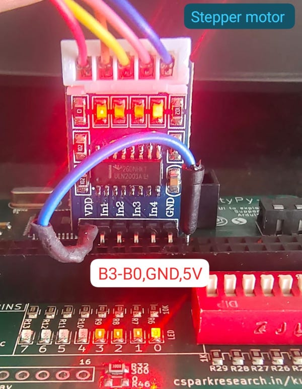
- Connect 4 wire, 2 phase stepper motor's A+,B+,A-,B- to PB0, PB1, PB2, PB3
- use the left and right arrow buttons to take single steps
- home button to return to original position
- the numeric entry field to move to a different position
## Video of the stepping sequence
LEDs are connected to PB0-PB3 to show the stepping signal outputs
<video controls width="600">
<source src="../images/stepper.webm"
type="video/webm">
Sorry, your browser doesn't support embedded videos.
</video>
## Applications
- Move a light sensor (TSL2561) along a diffraction pattern, and record the intensity profile
- Rotate the analyzer in a [Malus's law experiment](../malus), and record the intensity variation which corresponds to IoCos^2(Theta)$
# C Code for controlling
We'll be using the 28BYJ-48 stepper motor and its controller. It is unipolar.
B0 to B3 pins will be set as output, and the stepping sequence will be applied to
these pins.

The motor driver
```python
#include<avr/kp.h>
#define DELAY 5
#define STEPS 200
int main (void)
{
DDRB = 15; //For controlling the stepper motor
uint8_t steps[]={0b1100,0b0110,0b0011,0b1001}; // 12,6,3,9
uint16_t pos = 0;
for(;;)
{
for(pos=0;pos<STEPS;pos++){
PORTB=steps[2];
delay_ms(DELAY);
PORTB=steps[1];
delay_ms(DELAY);
PORTB=steps[0];
delay_ms(DELAY);
PORTB=steps[3];
delay_ms(DELAY);
}
for(pos=0;pos<STEPS;pos++){
PORTB=steps[0];
delay_ms(DELAY);
PORTB=steps[1];
delay_ms(DELAY);
PORTB=steps[2];
delay_ms(DELAY);
PORTB=steps[3];
delay_ms(DELAY);
}
}
return 0;
}
```
## Stepping Sequence
```commandline
// Connect pins B0 to B3 for the motor driver input.
wave drive sequence
Step B0 B1 B2 B3 Decimal
1 1 0 0 0 1
2 0 1 0 0 2
3 0 0 1 0 4
4 0 0 0 1 8
5 1 0 0 0 1 (Repeat)
Full Step
Step B0 B1 B2 B3 Decimal
1 1 1 0 0 3
2 0 1 1 0 6
3 0 0 1 1 12
4 1 0 0 1 9
5 1 1 0 0 3 (Repeat)
Half Step ( used in the C code below )
Step B0 B1 B2 B3 Decimal
1 1 0 0 0 1
2 1 1 0 0 3
3 0 1 0 0 2
4 0 1 1 0 6
5 0 0 1 0 4
6 0 0 1 1 12
7 0 0 0 1 8
8 1 0 0 1 9
9 1 0 0 0 1 (Repeat)
```
|
